LED Trunk Light
Illumination for Boot in Mini Cooper S (2013)
By TMTR September 23, 2018

My Mini Cooper S (2013) has a boot (trunk) light on the left side which is pretty small. Also, I built a storage box for the boot which raises the base of the trunk bottom effectively, so the angle of the light is less comparitively. On the whole, I found the existing light to be too dim and did not properly illuminate the trunk. I decided to replace the original incadescent light with a much, much brighter LED light fixture.
The light fixture I made is constructed from LED tape housed in a standard aluminum channel housing with plastic lens cover. The total wattage draw of the new fixture is a little less than that of the existing incadescent bulb (5 watts). I attached the housing to the shelf that raises and lowers with the trunk hatch (the one on strings that hides the contents of the trunkc when the hatch is closed. I attached the new LED light fixture with Velcro so it is removable. I put the fixture on a cord that is rolled up and with a plug, so that the light fixture and shelf can be removed as easily as originally when needed. The cord also has some length so as to allow for removing the light and using it around the vehicle for emergency road side repairs. The end result is a much brighter illumination of the boot.
Schematic ...
The schematic is very simple; it only looks complicated because I have included a lot of information on the various parts and shown parts which are not usually shown on schematics. Basically, the 12 VDC feed that goes to the existing trunk light, which is switched by the trunk opening and closing, is used to provide a 12 VDC feed that in turn is controlled by a manual switch. This switched feed goes to the new LED light. The switch is not really required and can be omitted if you choose to. A fuse is used to prevent any undesired shorts. The feed to the existing light comes from what I believe to be a controller and not a simple relay, so I kept the wattage of the new light fixture less than that of the existing bulb and replaced the existing bulb in it's entirety with the new LED light fixture so as to not overload the controller. The below image of the schematic can be downloaded as a PDF with clickable links to Mouser.com for the various parts. Feel free to source your own and substitute as desired.
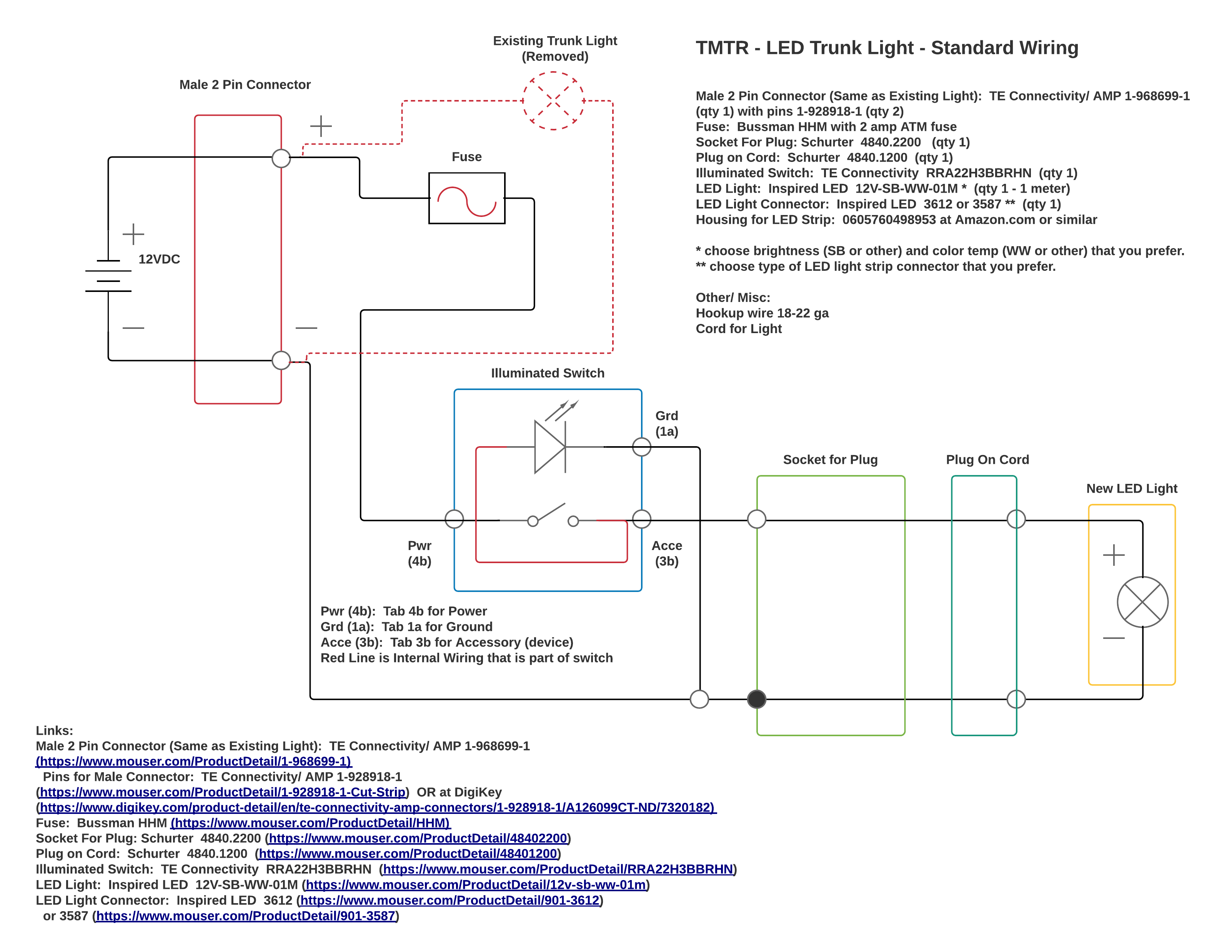
Electrical Schematic - Wiring Option 1 - Illuminated Switch Light goes on and off with LED Light. PDF version: Download Schematic 1
Replace original trunk light
Addition of LED Light in trunk tied in place of existing trunk light ...
Issues to Consider ...
As I mentioned above, the existing light's power source I believe to come from a controller and not a simple relay, though I have yet to find a schematic to verify that. I'm basing this understanding on stuff I have read at various community forums for Mini's. So, for me, I chose to proceed on the basis that I was not going to exceed the power draw of the original light bulb, which in my Mini, I found to be 5 watts. 5 watts of LED illumination is a lot, so there was no issue with retaining this design consideration.
As kind of an aside, but worth mentioning, is that the trunk light power source times out after a length of time with the trunk hatch open. So if you are working on it for a while and find no power, keep that in mind. A simple closing and re-opening of the trunk resets that timer.
Discussion of Parts ...
The parts used are listed on the schematic shown above and also downloadable as a pdf with clickable links to Mouser.com where these can be purchased. They are also available at other online suppliers such as Digikey and Arrow. I went through various schemes for how to design the light. The actual light was pretty straight forward from the start. I decided on LED tape lighting. I was thinking of just adhering the LED tape to the shelf above the trunk but opted for getting a housing for the tape. Both of these parts are listed on the schematic as well. What ended up requiring more thought was how to mount the connection point and switch. At the simpliest, you could tap into the plus and negative wires going to the existing light using T-taps and tie these to the new light fixture without any additional components. If you are opting for this route, I would recommend at least and inline fuse on the positive wire. I wanted to have the light fixture removable, so I required a plug and socket for the cord going to the new fixture. I also wanted a switch to control this light. The switch I got is illuminated by a 12 VDC lamp and can be wired to be always lit up or lit up only when the switch is in the On position. For mounting the switch and socket, I thought about making holes in the existing plastic lining on the trunk in one of two locations. The first was below the existing light. When thinking about this option, I figured I would place a small piece of wood behind the lining in order to drill through the lining with some spade bits. I got fiber washers of the appropriate size in order to provide for a bigger collar for both the switch and socket. I ended up not using these washers though. The second and concurrent idea was to do almost the same scheme but drilling through the removable access plastic panel in the trunk located below the existing light. Alhough not as ideal for me in terms of location, since it was more visible and in an area that would be covered often by other stuff in the trunk, I was considering this location for two reasons. First was the fact that this part could be replaced fairly cheaply and quickly down the road and second, the drilling would be easier. Based on pricing that I got online, the cost to replace the whole lining piece versus the access panel only was negligible. Still, replacing the access panel requires almost no work. IN the end, I decided to do no drilling, and instead make a plate to go over the hole where the existing trunk light is.
I used a piece of ABS plastic in a matte textured finish that I already had. I cut the plate to size using a saw and drilled the holes for both the socket and the switch. Velcro holds the plate in place. I only needed to put velcro on the plate since the existing plastic lining of the trunk has a fussy material that the hook half of the velcro would adhere to. I made the plate being sure to cover all exposed metal on the connectors and wiring that might come in contact with the car chassis. The last bit of design was how to wire into the existing feed from the controller that goes to the existing light.
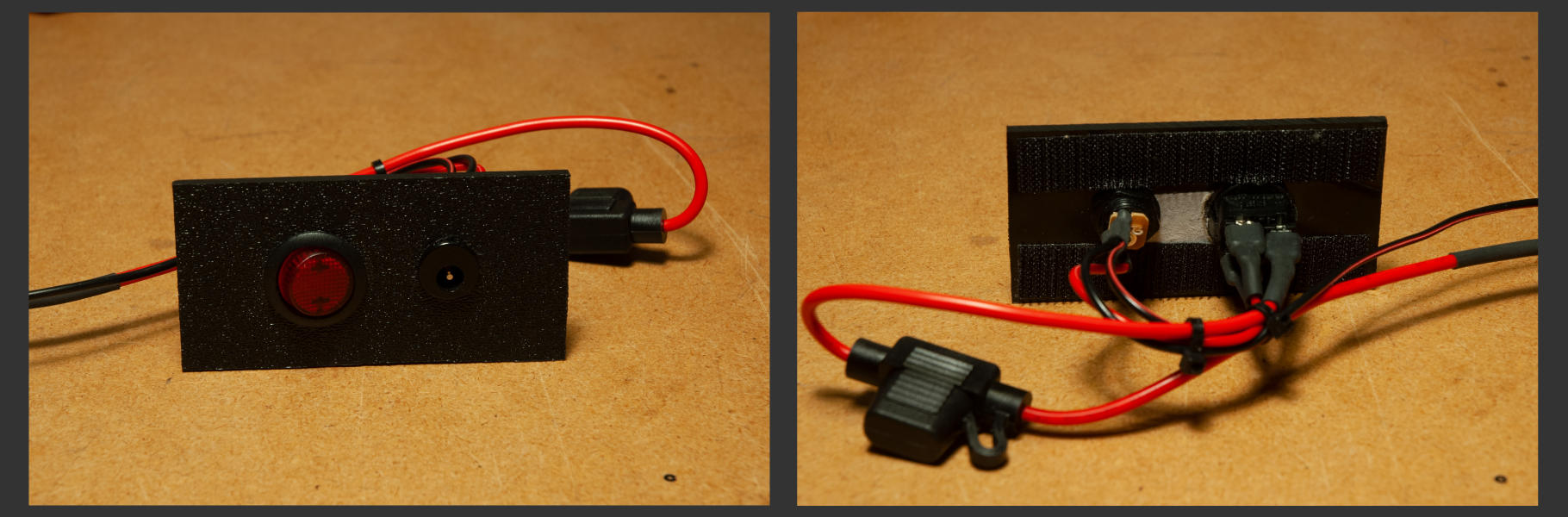
New Control Plate for Trunk Light
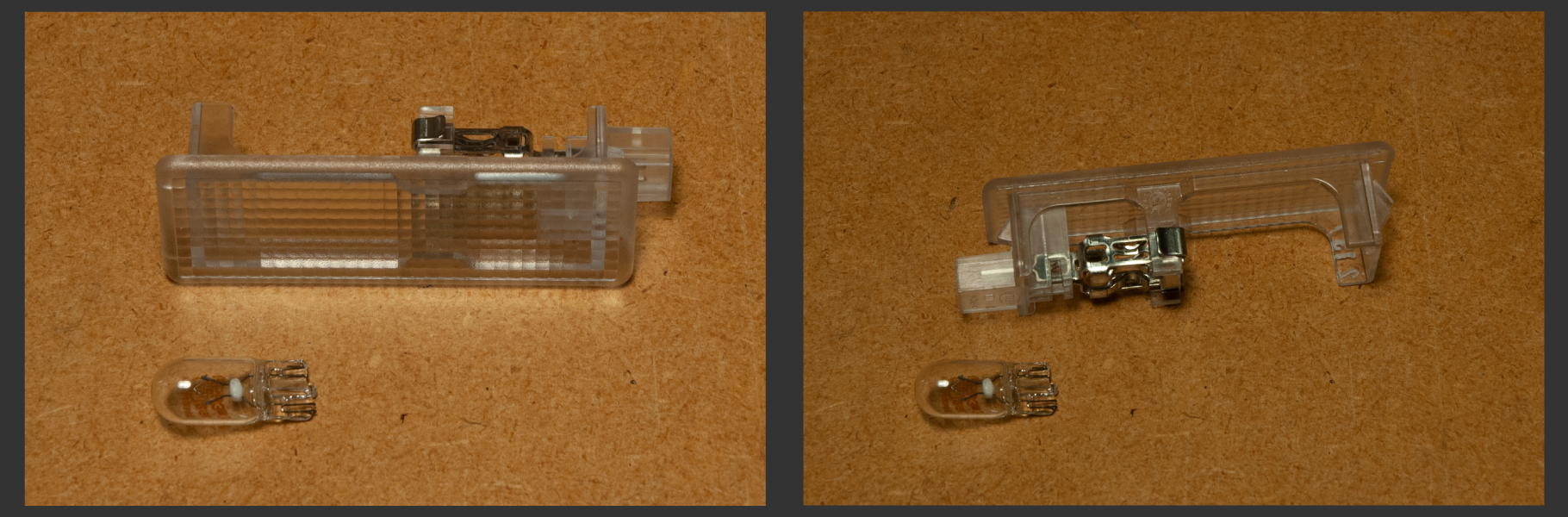
Existing Light to be Removed
The part of this project that required the most amount of searching was getting a connector that fit right onto the existing wire connector that attaches to the existing trunk light. The connector would have to be in the same form factor as the connector portion of the plastic housing that is the light. After much searching and based on other connectors in the Mini, I found a TE connector that mates with the existing connector on the wire. That connector is noted in the schematic where it is referred to as "Male 2 Pin Connector". It is made by TE Connectivity/ AMP with a part number of 1-968699-1 with 2 pins of part number 1-928918-1. The pins can be crimped onto the wire of suitable gauge using small pliers. There are two sets of tabs to be bent down and when the wire is securely fastened to the pins, the pins are inserted into the housing. Removing the pins from the housing requires you to push down on the metal tabs that are on the actual pins through a hole in the plastic housing. There is also a secondary plastic locking tab that is part of the housing which gets pushed down to lock in place and can be opened by prying up on the plastic tab. On the other ends of the wires, I put small quick disconnects. Note in the picture that I put the female disconnect on one wire and male on the other and had the corresponding mating part on the other set of wires leading to the switch plate that I made. I made sure I used the female disconnect on the positive wire so that when covered in heat shrink, no exposed metal is on the positive lead. When I put on the heat shrink I purposefully overlapped the end of the disconnect with heat shrink so it would curl under and cover the metal of the disconnect fully.
By TMTR September 23, 2018
By submitting your comment(s) using the form(s) on this website, you agree to the following:
- You grant the operator(s) of this website unrestricted permission to use your comment(s) publicly on this website unless you selected to make your comment a 'Private' comment as submitted on the comments form.
- For 'Public' marked comments, you grant the operator(s) of this website editing priviledges in so far as the operator(s) may selectively shorten the comment and and omit portions in an editorial way.
- Unless you specifically grant permission to add your optional email address, as enterred in the form, to our mailing list, your email address will not be utilized in any manner. Furthermore, the supplied email address will not be made public through any of our actions.
- You agree to provide relevant and appropriate comments as related to this website. Your comments should be of a manner which is constructive to the subject matter of this site. Your comments should refrain from use of inappropriate language.
- Not all comments which are indicated as 'Public' will be made publicly available on this site. The operator(s) of this site retain complete editorial judgement for which comments are to be added to this site. All comments are reviewed prior to posting.